I had a great time building the NorCal 40B and I have made contacts with the little ~2 watts output. However , it needs a little more punch to get out of my attic and to contact other than parks. Enter the 10 watt Pacific Antenna amp. I have not commented on this to date because if I have issues with a product I tend to look deeply within to see what mistakes I have made before pointing the finger elsewhere. My kit build track record has been good other than an obvious bonehead mistake on the TR-25 build (which was quickly remedied by great customer service).
As a retired accountant with very little test equipment trouble shooting is not always the easiest. An amp is so simple one would think getting it operational would be easy. Well not in this case. I have gotten through some issues, but the thing is just not stable. I reached out to the company early on with my first problem (which I have sorted). PACIFIC ANTENNA HAS NO CUSTOMER SERVICE!!! So far I have nothing but a PCB headed to the recycle bin.
In keeping with no mods to the HW-8 a small LM386 audio amp was constructed (kit) and placed in-line from the headphone jack on 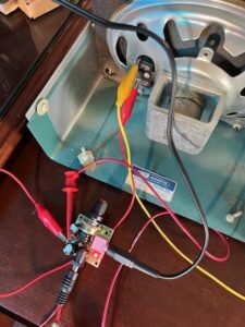 the HW-8 to my old school Heathkit Speaker. The first picture is the amp in the test phase and the second pictures shows the old speaker/LM386 amp in place on top of the HW-8. The amp is powered for now by a nine volt battery. The battery is sitting to the right clipped in waiting for a holder to arrive.
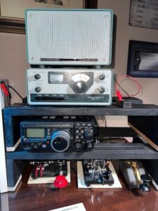
Well, the HW-8 works, but it needs help. I guess that is to be expected for a radio of its vintage. The receiver is hot, but too many of the stations heard are in one spot (hi). I worked stations in the first hour of this past weekend’s WES, but it was difficult. I listened to the radio on 40 meters during the daylight hours on a web SDR receiver and the signal sounded clean.
I am not sure where to go from here. Alignment is in order, but lack of test equipment and aging coil cores have me concerned. I do have the alignment tool I believe from my HW-7 build so so many years ago but am just not sure whether it is worth the risk of the cores breaking. Having the VFO a lot closer to frequency would be nice. Also, I have to get headphones that are a lot more comfortable to wear or take the plunge and modify the radio.
For some reason I just feel bugs are the best keys to use with my QRP radios. It is not for the lack of keyers I could use.
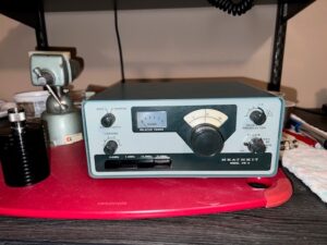 The HW-8 arrived at ~19:15 local time last night. It was well packed and in very good physical condition. The first step was to put Anderson Powerpoles on the power leads. Next was to turn the HW-8 on and see how my WWII headphones worked after being on the shelf unused for over 55 years. They worked like a charm! So far, I only tried the little radio on 40 meters. I listened and had a POTA contact with a park in Texas. All I noted so far is (only on 40 meters):
- The received is hot.
- The dial is a lot more off frequency than the seller said it was.
- The meter pins when tuning for peak output. Note: The pinning is the result of a cold solder joint on R303 in the meter circuit.
- My power meter shows an output of 2 watts.
- Most concerning is a low-level signal just above the tuned frequency being generated in receive. It was detected on the P3 when testing the radio into a dummy load. It was not seen when the HW-8 was transmitting into the antenna. The signal may be too weak to be detected when the K3 is not on the antenna. Further research is required. Note: This signal is not being transmitted over the air. Also, it appears this is normal internal generated RF.
Yes, it was fun to build and operate, but it is just not right. The FREQ-Mite audio level is too high (even after increasing the inline resistor to one megohm), and the RF power output is too low. Lacking any real test equipment (such as a means to measure inductance) I am not sure the little radio will ever be what should be. The question is: will the NorCal 40B make its way back to the operating desk or just become a knickknack on the shelf? Time will tell, but at this point my hopes are not very high.
Footnote: The morning after the above post just before pulling the NorCal 40B offline I had a very nice QSO with a station about 580 miles away. So even at a max of 1.5 watts out I can still work other stations and have a real QSO. It is important to point out the other station was very loud in North Georgia.
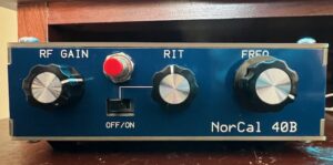 This is the semi-finished NorCal 40B. (I chose to place the FREQ-Mite’s activation bottom above the RIT switch.) I am not sure the little radio will ever be finished. It is more and experiment than a anything else. I added up to a one megohm resistor to the audio line from the FREQ-Mite and the level is still too high. The power output appears to be too low, but my measuring devices are not all that precise. I do not have any real test equipment just a DMM, an Elecraft W1 Power Meter (kit built) and a home-built RF probe. That said it was fun to build, enjoy following all the web chatter about the radio and I can have nice QSO’s with the little thing. It was especially enjoyable and interesting to build the transceiver by circuit stage. I am ready to build more stuff!
The FREQ-Mite is installed in the NorCal 40B. It works, but somehow, I lost 25% of my power output. When there is only 2 watts losing 25%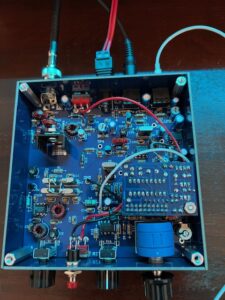 is a big deal. As I have said many times it is the journey not the destination, this is starting to feel like an endless trip.
The frequency appears to be close to the display on my K3. Also, I have to increase the resistor value in the audio line as the volume is too high.
The FREQ-Mite is working in the test mode. Now to mount it in the NorCal 40B.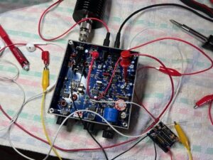
The FREQ-Mite was received and is on the bench (actually a table). It came fast and in perfect condition. A parts inventory showed all was received in order.
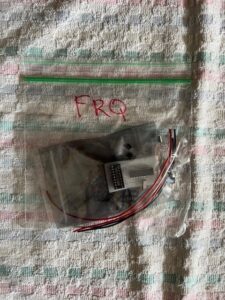
FREQ-mite received and ready to be built
I started to put the parts on the board. I tend to build these kits slowly as it is the journey not the destination. Although there has to be a destination that includes a functional and useful end result.
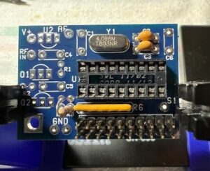
Freq-Mite build in process
Yes, two watts is useable with an attic antenna for a nice QSO. A little rig like the NorCal 40B goes very nicely for a long rag chew when things are just right (band conditions, time of day and distance). I had just such a QSO with a station about 340 miles away during the daytime hours. Great chat until my fist decided it was time.
This is my temporary QRP r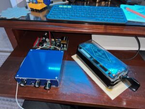 adio setup. The keyboard normally resides on the pullout shelf. (One screw still to be put in the top cover -hi hi.) Behind the radio is my Elecraft W1 Power Meter and the bug is a Lafayette Radio MS-435 circa the early 1960’s.


